Pumping (oil+air+water) flow
2019 – 2020
Supervised by:
د. محمود سالم
By:
عمر عبد المحسن عبد الغفار السمان
Abstract
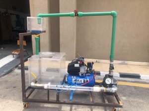
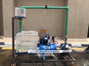
This project targets the study of the effect for pumping both oil and water, which is operated by a centrifugal pump. Theory of operation: There are several flow rates that are going to be controlled by a primary valve from the tank. They will pass through the circuit’s pipelines, control valves, pressure gauges and finally the pump. So, the pressure gauge’s readings can be plotted before and after the used pump. Therefore, the pressure heads will be calculated for every specified amount of flow rate depending on the opening angle of the control valve. In addition, the (H-Q) curves can be estimate for the new pump performance. The components are two transparent tanks, transparent pipeline, centrifugal pump, two control valves and three pressure gauges. The first tank is cubed with 23cm dimensions. The second tank is 50cm length and width and 60cm height. The centrifugal pump has 1.63 H.P. Electric motor has 1200 round/minute with a single shaft that acts as a mixer. The project construction contains pipelines, elbows, joints and metal buckles, which welded with each other to create the stand for the project.
Components:
- 2 Tanks with volume near to 1.5,
- 2 inch diameter St. Steel pipes with about 3.5 m length,
- 2 inch diameter transparent PVC pipe with about 2 m length
- 63 hp centrifugal pump,
- 1200 rpm electric motor with a shaft that acts as a mixer,
- Elbows and joints for the pipe line construction,
- Metal buckles welded with casters so as to act as a stand for the whole circuit,
- 2 control valves to control the flow rate at the tank,
- Three pressure gauges.
Chapter (1) Word Pdf Presentation
Final Book Word Pdf Presentation


